
Serial Communication
So far each Arduino has worked alone. In this experiment boards and modules talk to each other, one bit at a time, over a few wires. You use the two links found on almost every microcontroller: a UART, two wires between two devices, and I²C, one shared two-wire bus with many devices on it, each with its own address.
Objectives
- Describe a UART frame: start bit, data bits, stop bit and baud rate.
- Link two Arduino Megas with
Serial1, crossing TX and RX, and send characters between them. - Explain how I²C addresses devices on a shared bus, and find a device's address with a scanner.
- Show text and numbers on an I²C LCD.
- Read a value from a second Arduino over I²C, sent as two bytes.
Before the lab
Finish Experiment 3: this experiment uses the Serial Monitor, INPUT_PULLUP buttons and analogRead(). Work in pairs, with two Megas and two laptops, or both boards plugged into one laptop.
Background
UART
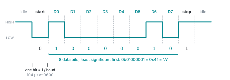
A UART (universal asynchronous receiver-transmitter) sends bytes one bit at a time down one wire, TX, and receives them on another, RX. There is no clock wire. Instead both sides agree on the speed beforehand, the baud rate in bits per second, and each byte is wrapped in a frame that tells the receiver where it starts and ends:
| Part | What it is |
|---|---|
| Idle | The line rests HIGH between frames |
| Start bit | One LOW bit: "a byte is coming". The receiver starts its timing here. |
| Data bits | Usually 8, least significant bit first |
| Parity bit | Optional extra bit for error checking; usually left out |
| Stop bit | One HIGH bit, back to idle |
The usual setting, and the Arduino default, is 8N1: 8 data bits, no parity, 1 stop bit. That is 10 bits on the wire per byte, so at 9600 baud a byte takes about 1 ms. If the two sides use different baud rates, the receiver samples at the wrong times and you get garbage.
Serial ports on the Mega
The Mega has four hardware UARTs. Serial is the one you already know: it goes over the USB cable to the Serial Monitor, and also to pins 0 and 1. To talk to another board, use one of the others, so the USB link stays free for uploading and printing:
| Port | TX pin | RX pin | Notes |
|---|---|---|---|
Serial | 1 | 0 | Shared with USB: leave it for upload and the Serial Monitor |
Serial1 | 18 | 19 | Used in this experiment |
Serial2 | 16 | 17 | |
Serial3 | 14 | 15 |
Every port has the same functions; only the name changes:
| Function | Effect |
|---|---|
Serial1.begin(9600) | Start the port at 9600 baud. Both boards must use the same number. |
Serial1.available() | How many received bytes are waiting to be read |
Serial1.read() | Take one received byte out of the buffer (−1 if there is none) |
Serial1.write('A') | Send one byte, as it is |
Serial1.print(65) | Send a value as readable text: here the two characters 6 and 5 |
Serial1.println(65) | The same, followed by a new line |
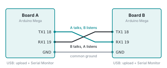
Wire two boards crossed: each one's TX goes to the other's RX, because what one says the other must hear. Join the grounds too, or the receiver has no reference for HIGH and LOW:
I²C
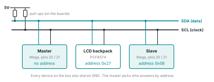
A UART joins exactly two devices. I²C (inter-integrated circuit, said "I squared C") puts many devices on the same two wires:
| Wire | Mega pin | Use |
|---|---|---|
| SDA | 20 | Data, in both directions |
| SCL | 21 | Clock, always driven by the master |
One device is the master: it makes the clock and starts every transfer. Every other device is a slave with its own 7-bit address, 1 to 127, and it only answers when the master calls that address. Both wires have pull-up resistors to 5V, so an idle bus reads HIGH; the LCD module and the Mega already have them.
Every transfer has the same shape. The master sends START, then the slave's address and one bit for the direction, write or read. The slave with that address answers with an ACK (acknowledge). Then the data bytes follow, each one acknowledged, and the master ends with STOP:
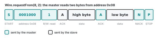
If no device has the address, nobody sends the ACK. A scanner uses that: it calls every address from 1 to 126 and reports the ones that answer.
The Wire library, built into the IDE, does all of this for you:
| On the master | Effect |
|---|---|
Wire.begin() | Join the bus as the master |
Wire.beginTransmission(addr) ... Wire.endTransmission() | Send to a slave. endTransmission() returns 0 if the slave answered ACK. |
Wire.requestFrom(addr, n) | Ask the slave for n bytes |
Wire.available(), Wire.read() | How many requested bytes arrived; take one |
| On a slave | Effect |
|---|---|
Wire.begin(addr) | Join the bus as a slave at this address |
Wire.onRequest(f) | Call function f whenever the master asks for data |
Wire.write(b) | Inside f: send byte b to the master |
The I²C LCD
The LCD is a 16-column, 2-row text display. Its backpack board turns I²C into the LCD's parallel signals, so the display needs only four wires: GND, VCC (5V), SDA and SCL. The backpack's address is usually 0x27, sometimes 0x3F; the scanner tells you which. The blue potentiometer on the back sets the contrast.
Install LiquidCrystal I2C by Frank de Brabander from the Library Manager (how). Then:
| Function | Effect |
|---|---|
LiquidCrystal_I2C lcd(0x27, 16, 2) | An LCD at address 0x27, 16 columns, 2 rows |
lcd.init(), lcd.backlight() | Start it and turn on the backlight; once, in setup() |
lcd.setCursor(col, row) | Move to a column (0–15) and row (0–1) |
lcd.print(x) | Write text or a number from there on |
lcd.clear() | Blank the display and return to (0, 0) |
Sending a number bigger than a byte
I²C, like a UART, moves single bytes, 0 to 255. An analogRead() result goes up to 1023, so it needs two bytes. Split it into a high byte and a low byte, send both, and join them again at the other end:
int value = 700;                 // 0b10 1011 1100
byte high = value >> 8;          // the top bits:    0b10       = 2
byte low  = value & 0xFF;        // the bottom 8:    0b10111100 = 188
int back  = (high << 8) | low;   // 2 × 256 + 188 = 700 again
Materials
- 2 × Arduino Mega 2560 and USB cables
- Breadboard and jumper wires
- 16×2 LCD with an I²C backpack
- Push button
- LED and 220 Ω resistor
- 10 kΩ potentiometer
Examples
Example 1: two boards over Serial1
Wire the two boards as in the figure: pin 18 of each to pin 19 of the other, and GND to GND. Plug in both USB cables. Each board shows up as its own port: open two IDE windows (File → New Sketch) and pick a different port in each.
Upload this to board A:
// sender.ino: board A. Send a counter to board B over Serial1, once a second.
// Board A pin 18 (TX1) -> board B pin 19 (RX1), pin 19 -> pin 18, GND -> GND.

int count = 0;

void setup() {
  Serial.begin(9600);    // USB: this board's own Serial Monitor
  Serial1.begin(9600);   // pins 18/19: the link to board B. Same baud on both boards.
}

void loop() {
  Serial1.println(count);              // to board B
  Serial.print("Sent ");               // to our own monitor, so we can see it
  Serial.println(count);
  count++;
  delay(1000);
}
And this to board B:
// receiver.ino: board B. Pass everything that arrives on Serial1 on to the Serial Monitor.
// Wired to board A as in sender.ino.

void setup() {
  Serial.begin(9600);    // USB: this board's Serial Monitor
  Serial1.begin(9600);   // pins 18/19: the link to board A
}

void loop() {
  if (Serial1.available() > 0) {   // a byte has arrived from board A
    char c = Serial1.read();       // take it out of the receive buffer
    Serial.write(c);               // and show it, unchanged
  }
}
Open the Serial Monitor of each window at 9600 baud. Board A prints Sent 0, Sent 1, ...; board B prints 0, 1, ... as they arrive over the wires. Pull out one of the TX–RX wires: board B stops, board A carries on.
Upload works with the link wired
Because the link is on Serial1, not pins 0 and 1, you can upload to either board without unplugging anything.
Example 2: I²C scanner and LCD
Wire the LCD to board A only:
| LCD backpack | Mega |
|---|---|
| GND | GND |
| VCC | 5V |
| SDA | 20 |
| SCL | 21 |
First find its address. Upload the scanner and open the Serial Monitor at 9600 baud:
// scanner.ino: list the address of every device on the I2C bus.
// LCD backpack: GND -> GND, VCC -> 5V, SDA -> pin 20, SCL -> pin 21.

#include <Wire.h>

void setup() {
  Wire.begin();          // join the bus as the master
  Serial.begin(9600);
}

void loop() {
  int found = 0;
  Serial.println("Scanning...");

  for (byte address = 1; address < 127; address++) {
    Wire.beginTransmission(address);   // START, then the address
    if (Wire.endTransmission() == 0) { // 0: a device answered with ACK
      Serial.print("Device at 0x");
      if (address < 16) Serial.print("0");
      Serial.println(address, HEX);
      found++;
    }
  }

  if (found == 0) Serial.println("No devices found");
  delay(5000);
}
It prints one line per device, for example Device at 0x27. Write your address down.
Now put that address in this sketch and upload it:
// lcd-hello.ino: text on a 16x2 I2C LCD, and a seconds counter on its second row.
// Wired as for scanner.ino. Library: "LiquidCrystal I2C" by Frank de Brabander.

#include <Wire.h>
#include <LiquidCrystal_I2C.h>

LiquidCrystal_I2C lcd(0x27, 16, 2);   // address from the scanner, 16 columns, 2 rows

void setup() {
  lcd.init();
  lcd.backlight();
  lcd.setCursor(0, 0);                // column 0, row 0
  lcd.print("Hello, BZU!");
}

void loop() {
  lcd.setCursor(0, 1);                // column 0, row 1
  lcd.print("Uptime: ");
  lcd.print(millis() / 1000);
  lcd.print(" s");
  delay(200);
}
The first row shows Hello, BZU! and the second counts seconds. If the backlight is on but no text shows, turn the contrast potentiometer on the back of the LCD.
Lab work
Each lab work uses two boards, so it has two starter sketches, one per board. They already work except for a few lines marked TODO. Copy each into its own IDE window, fill in the TODOs, and upload each to its board.
Lab work 1: a remote button
Press a button on board A and an LED lights on board B; release it and the LED goes off. Board A sends the character 1 when the button goes down and 0 when it comes up.
Keep the Example 1 link. On board A, wire a push button between pin 2 and GND. On board B, wire an LED on pin 8 through 220 Ω.
Board A:
// lab1-sender-starter.ino: Lab work 1, board A. Fill in TODO 1 and TODO 2.
// Button between pin 2 and GND. Serial1 wired to board B as in Example 1.

const int BUTTON_PIN = 2;
bool wasPressed = false;           // the button state the last time round

void setup() {
  pinMode(BUTTON_PIN, INPUT_PULLUP);
  Serial.begin(9600);
  // TODO 1: start Serial1 at 9600 baud
}

void loop() {
  bool pressed = (digitalRead(BUTTON_PIN) == LOW);   // LOW means pressed (pull-up)

  if (pressed != wasPressed) {     // the button has just been pressed or released
    wasPressed = pressed;
    if (pressed) {
      // TODO 2: send the character '1' to board B
      Serial.println("Sent 1");
    } else {
      Serial1.write('0');          // released: send '0'
      Serial.println("Sent 0");
    }
    delay(20);                     // let the contacts stop bouncing
  }
}
Board B:
// lab1-receiver-starter.ino: Lab work 1, board B. Fill in TODO 3 and TODO 4.
// LED on pin 8 through 220 ohm. Serial1 wired to board A as in Example 1.

const int LED_PIN = 8;

void setup() {
  pinMode(LED_PIN, OUTPUT);
  Serial.begin(9600);
  Serial1.begin(9600);
}

void loop() {
  if (Serial1.available() > 0) {
    char c = 0;                    // TODO 3: read one character from Serial1 into c

    Serial.print("Got ");
    Serial.println(c);

    // TODO 4: if c is '1' turn the LED on; if c is '0' turn it off
  }
}
Hints
- TODO 1: the same line as in Example 1:
Serial1.begin(9600); - TODO 2: copy the
'0'line just below it and change the character:Serial1.write('1'); - TODO 3:
char c = Serial1.read(); - TODO 4: two
ifs:if (c == '1') digitalWrite(LED_PIN, HIGH);and the same for'0'andLOW. Note the single quotes:'1'is the character,1is the number. - Board B's Serial Monitor shows every character it gets. If it shows nothing, the link is wired wrong; if it shows
1and0but the LED stays off, the problem is TODO 4 or the LED.
Lab work 2: a remote voltmeter
The slave board reads a potentiometer. The master board asks it for the reading over I²C twice a second, and shows the reading and its voltage on the LCD.
Keep the LCD on the master board, as in Example 2. On the slave board, wire the potentiometer: its two ends to 5V and GND, its middle pin (the wiper) to A0. Then join the two boards' SDA (20 to 20), SCL (21 to 21) and GND. The LCD and the slave are now on the same bus, at different addresses; the TX–RX wires from Lab work 1 can stay or go.
Slave board:
// lab2-slave-starter.ino: Lab work 2, the slave board. Fill in TODO 1.
// Potentiometer: ends to 5V and GND, wiper to A0. SDA, SCL and GND wired to the master.

#include <Wire.h>

const byte MY_ADDRESS = 8;         // this board's I2C address

void onRequest() {                 // runs when the master asks for data
  int reading = analogRead(A0);    // 0..1023: needs 10 bits, too big for one byte
  // TODO 1: send reading as two bytes, the high byte first, then the low byte
}

void setup() {
  Wire.begin(MY_ADDRESS);          // join the bus as a slave at this address
  Wire.onRequest(onRequest);       // call onRequest() on every request
}

void loop() {
  // nothing: onRequest() does all the work
}
Master board (put your LCD's address in it):
// lab2-master-starter.ino: Lab work 2, the master board. Fill in TODO 2, 3 and 4.
// LCD as in Example 2. SDA (20), SCL (21) and GND also wired to the slave board.

#include <Wire.h>
#include <LiquidCrystal_I2C.h>

const byte SLAVE_ADDRESS = 8;
LiquidCrystal_I2C lcd(0x27, 16, 2);   // your LCD's address from the scanner

void setup() {
  Wire.begin();                    // the master: no address
  Serial.begin(9600);
  lcd.init();
  lcd.backlight();
}

void loop() {
  Wire.requestFrom(SLAVE_ADDRESS, (byte)2);   // ask the slave for 2 bytes
  if (Wire.available() == 2) {
    byte high = Wire.read();       // first byte: the high byte
    byte low = Wire.read();        // second byte: the low byte

    int reading = 0;               // TODO 2: put high and low back together
    float volts = 0;               // TODO 3: convert reading (0..1023) to volts (0..5)

    Serial.print(reading);
    Serial.print("  ");
    Serial.println(volts);

    lcd.clear();
    lcd.setCursor(0, 0);
    lcd.print("Reading: ");
    lcd.print(reading);
    lcd.setCursor(0, 1);
    // TODO 4: print "Volts: " and then volts on this row
  }
  delay(500);
}
Hints
- TODO 1: two lines, as in Sending a number bigger than a byte:
Wire.write(reading >> 8);thenWire.write(reading & 0xFF); - TODO 2:
int reading = (high << 8) | low; - TODO 3: the formula from Experiment 6:
float volts = reading * 5.0 / 1023; - TODO 4:
lcd.print("Volts: ");thenlcd.print(volts); - Run the scanner from Example 2 on the master first: it should now find two devices, your LCD and
0x08.
Check your numbers
- High byte 3 and low byte 255 give 3 × 256 + 255 = 1023, which is 5.00 V.
- With the knob in the middle, the reading is about 512: high byte 2, low byte 0, about 2.50 V.
- With the knob at the GND end, both bytes are 0 and the LCD shows 0.00 V.
Common problems
| Symptom | Cause and fix |
|---|---|
| Board B receives nothing | TX and RX are not crossed (18 goes to 19), the grounds are not joined, or one board says Serial instead of Serial1. |
| Board B receives garbage | The two begin() calls use different baud rates. |
| The Serial Monitor shows garbage | Its baud rate does not match Serial.begin(). |
| Upload fails with the boards linked | Something is wired to pins 0 or 1. Move the link to 18 and 19. |
| The LED in Lab work 1 never changes | The comparison uses 1 instead of '1'. |
| The scanner finds no devices | SDA and SCL are swapped or not on 20 and 21, or the LCD has no 5V or GND. |
| The LCD lights but shows no text, or a row of blocks | Turn the contrast potentiometer on its back. Or the address in the sketch is not the one the scanner found. |
LiquidCrystal_I2C.h: No such file or directory | The library is not installed. See Install a library. |
| Lab work 2 shows nothing, or 0 all the time | The slave is not at 8, its SDA, SCL or GND is not joined to the master's, or TODO 1 sends nothing. |
| The reading is right but the volts are 0.00 | 5 was written instead of 5.0, so the division is done in integers. |
Things to try
- Change the baud rate on board B only in Example 1, to 4800, and look at what arrives. Then set both to 115200.
- Try parity:
Serial1.begin(9600, SERIAL_8E1)on both boards adds an even-parity bit. Set one board toSERIAL_8O1and see what happens. - Make Lab work 1 two-way: a button and an LED on each board, each button lighting the other board's LED.
- Make the master write to the slave:
Wire.beginTransmission(8); Wire.write(x); Wire.endTransmission();on the master, andWire.onReceive(f)withWire.read()insidefon the slave. Use it to set an LED's brightness on the slave from a potentiometer on the master. - Scroll a message longer than 16 characters across the LCD with
lcd.scrollDisplayLeft(). - Read about SPI, the third common link: four wires (MOSI, MISO, SCK and one chip-select per device), faster than I²C, used by SD cards and many displays. The Mega's SPI pins are 50 to 53, and the
SPIlibrary is built in.