
ARM Assembly and Keil uVision5
In this lab you write your first ARM assembly programs for an ARM Cortex-M4 and run them in the Keil simulator. You learn the skeleton every program needs, then use the debugger to watch registers and flags change one instruction at a time.
Objectives
- Create, build and debug an assembly project in Keil uVision5.
- Know the Cortex-M4 core registers and what the
N,Z,CandVflags mean. - Use the move, arithmetic, logic, shift and load/store instructions.
Before the lab
Read the Keil setup guide. It shows how to create a project and use the debugger, which this page assumes.
Background
Anatomy of a program
Every program in Experiments 1 and 2 has the same skeleton. Only the part after Reset_Handler changes.
; first.s: the smallest complete program. Copy this skeleton for every lab.

        PRESERVE8
        THUMB

; ---- Vector table: the first two words the CPU reads at reset ----
        AREA    RESET, DATA, READONLY
        EXPORT  __Vectors
__Vectors
        DCD     0x20001000          ; initial stack pointer
        DCD     Reset_Handler       ; address of the first instruction to run
        ALIGN

; ---- Program ----
        AREA    MYCODE, CODE, READONLY
        ENTRY
        EXPORT  Reset_Handler
Reset_Handler
        ; your code starts here
        MOV     R0, #12

STOP    ADD     R0, R0, #4          ; R0 grows by 4 every time round
        B       STOP

END| Line | Meaning |
|---|---|
PRESERVE8, THUMB | Keep the stack 8-byte aligned and assemble Thumb instructions, the only kind a Cortex-M runs. |
AREA RESET, DATA, READONLY | Start a block of memory named RESET. The linker puts it at address 0. |
__Vectors and its two DCDs | The vector table. At reset the CPU loads the first word into the stack pointer and jumps to the address in the second. |
AREA MYCODE, CODE, READONLY | Start the block that holds your instructions. |
ENTRY, EXPORT Reset_Handler | Mark where execution starts, and let the linker see that label. |
STOP B STOP | Branch to itself forever. There is no operating system to return to, so a program must never "fall off" its end. |
END | End of the source file. Anything after it is ignored. |
Columns matter
A label must start in column 1. Instructions and directives must be indented by at least one space or a tab. Write MOV R0, #12 in column 1 and the assembler reads MOV as a label and complains about an unknown opcode.
Each instruction line has the form:
label OPCODE destination, operand1, operand2 ; commentCore registers
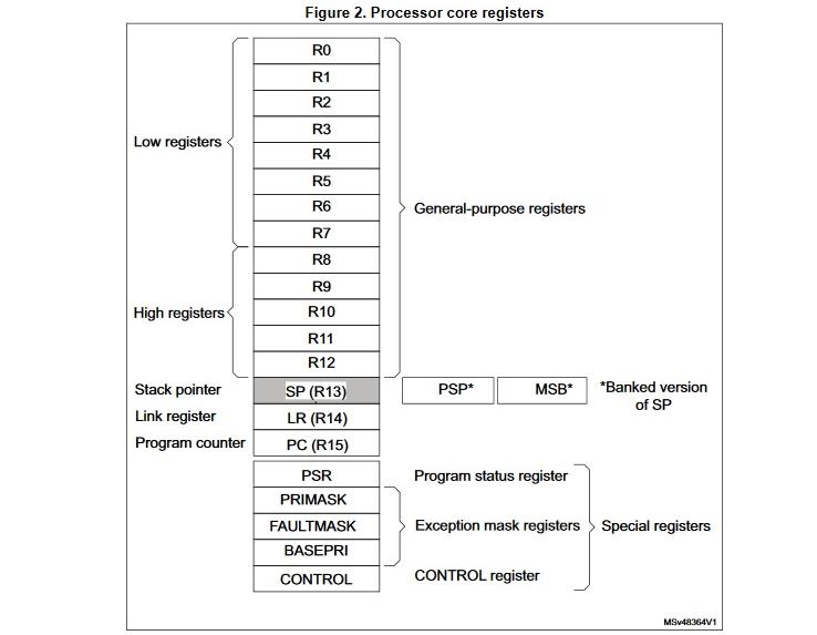
- R0–R12: general-purpose. Use them freely.
- R13 (SP): the stack pointer. It is loaded from the first word of the vector table.
- R14 (LR): the link register, which holds the return address after a
BLcall (Experiment 2). - R15 (PC): the program counter, the address of the next instruction.
- xPSR: the program status register. Its top four bits are the condition flags:
| Flag | Set to 1 when the result… | Read it as |
|---|---|---|
| N | has bit 31 set | negative, if the numbers are signed |
| Z | is exactly zero | equal, after a compare |
| C | carried out of bit 31 on an add, or did not borrow on a subtract | unsigned overflow on an add |
| V | has the wrong sign, e.g. two positives added to a negative | signed overflow |
Instructions only update the flags when you append S: ADDS sets them, ADD does not. Compare instructions (CMP, Experiment 2) always set them.
Memory map
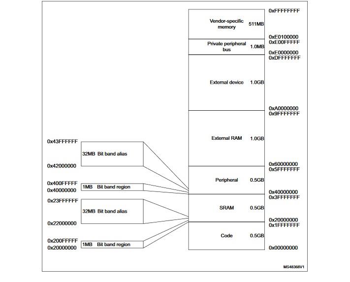
In the Keil ARMCM4 simulator, your code and constants live from address 0x00000000 (the code region) and RAM starts at 0x20000000. The stack pointer 0x20001000 sits 4 KB into RAM, and variables you declare in a READWRITE area land at 0x20000000.
Instruction quick reference
Keep this open while you work. Rd is the destination, Rn/Rm are source registers, and #imm is a constant.
Move
| Instruction | Effect |
|---|---|
MOV Rd, #imm / MOV Rd, Rm | Rd = imm / Rd = Rm |
MVN Rd, #imm | Rd = NOT imm (bitwise inverse) |
MOVT Rd, #imm16 | Replace the top 16 bits of Rd, keep the bottom 16 |
MOV32 Rd, #imm32 | Any 32-bit constant (assembles to MOVW + MOVT) |
LDR Rd, =imm32 | Any 32-bit constant or label address, loaded from a nearby constant pool |
Arithmetic
| Instruction | Effect |
|---|---|
ADD Rd, Rn, Rm | Rd = Rn + Rm (the last operand can also be #imm) |
SUB Rd, Rn, Rm | Rd = Rn − Rm |
RSB Rd, Rn, #imm | Rd = imm − Rn (reverse subtract) |
MUL Rd, Rn, Rm | Rd = Rn × Rm (low 32 bits) |
UMULL RdLo, RdHi, Rn, Rm | 64-bit unsigned product in RdHi:RdLo (SMULL for signed) |
UDIV Rd, Rn, Rm / SDIV Rd, Rn, Rm | Rd = Rn ÷ Rm, unsigned / signed, rounded toward zero |
Logic and shifts
| Instruction | Effect |
|---|---|
AND, ORR, EOR Rd, Rn, Rm | Bitwise AND, OR, XOR |
BIC Rd, Rn, Rm | Rd = Rn AND NOT Rm, clears the bits set in Rm |
ORN Rd, Rn, Rm | Rd = Rn OR NOT Rm |
LSL Rd, Rm, #n / LSR Rd, Rm, #n | Logical shift left / right by n bits (×2ⁿ / unsigned ÷2ⁿ) |
ASR Rd, Rm, #n | Arithmetic shift right, keeps the sign (signed ÷2ⁿ) |
ROR Rd, Rm, #n | Rotate right |
Load and store: the only instructions that touch memory.
| Instruction | Effect |
|---|---|
LDR Rd, label | Rd = the word stored at label |
LDR Rd, =label | Rd = the address of label |
LDR Rd, [Rn] | Rd = the word at the address in Rn |
LDR Rd, [Rn, #4] | Rd = the word at Rn + 4 |
STR Rd, [Rn] | Store Rd at the address in Rn |
LDRB / STRB | Same, for a single byte |
Data directives
| Directive | Effect |
|---|---|
name DCD 5, 7, -3 | Reserve 32-bit words with these initial values |
name DCB "Hi", 0 | Reserve bytes: a string, here null-terminated |
Why MOV R0, #0x12345678 does not assemble
An instruction is only 16 or 32 bits wide, so there is no room for an arbitrary 32-bit constant. MOV accepts any 16-bit value, or a small set of 32-bit patterns such as 0xFF000000 and 0xFFFFFFFF. For anything else, use MOV32 or LDR Rd, =value. Check the Disassembly window to see what the assembler actually produced.
Examples
For each example, create a project (Keil → Create a project), paste the code, build, start debugging and step with F11. Predict each register before you step.
The first program
Use first.s from Anatomy of a program. Step through it and watch R0 start at 12 and grow by 4 on every loop.
Example 1: arithmetic
Compute f(x) = 5x² − 6x + 8 for x = 7.
; example1.s: f(x) = 5x^2 - 6x + 8 for x = 7

        PRESERVE8
        THUMB

        AREA    RESET, DATA, READONLY
        EXPORT  __Vectors
__Vectors
        DCD     0x20001000          ; initial stack pointer
        DCD     Reset_Handler       ; reset vector
        ALIGN

        AREA    MYCODE, CODE, READONLY
        ENTRY
        EXPORT  Reset_Handler
Reset_Handler
        MOV     R0, #7              ; x = 7

        MUL     R1, R0, R0          ; R1 = x^2
        MOV     R4, #5
        MUL     R1, R1, R4          ; R1 = 5x^2

        MOV     R5, #6
        MUL     R2, R0, R5          ; R2 = 6x

        SUB     R3, R1, R2          ; R3 = 5x^2 - 6x
        ADD     R3, R3, #8          ; R3 = 5x^2 - 6x + 8

STOP    B       STOP
        END
When it reaches STOP, R3 should hold 211 (0xD3).
Example 2: memory
Load two constants from flash, compute (a + b − 1) × 4, and store the result in a RAM variable.
; example2.s: read two constants, compute (a + b - 1) * 4, store it in RAM

        PRESERVE8
        THUMB

        AREA    RESET, DATA, READONLY
        EXPORT  __Vectors
__Vectors
        DCD     0x20001000          ; initial stack pointer
        DCD     Reset_Handler       ; reset vector
        ALIGN

        AREA    MYRAM, DATA, READWRITE
SUM     DCD     0                   ; one word of RAM, at 0x20000000

        AREA    MYCODE, CODE, READONLY
        ENTRY
        EXPORT  Reset_Handler
Reset_Handler
        LDR     R1, NUM1            ; R1 = value stored at NUM1
        LDR     R2, NUM2            ; R2 = value stored at NUM2

        ADD     R0, R1, R2
        SUBS    R0, R0, #1
        LSLS    R3, R0, #2          ; shift left by 2 = multiply by 4

        LDR     R4, =SUM            ; R4 = address of SUM
        STR     R3, [R4]            ; SUM = R3
        LDR     R6, [R4]            ; read it back to check

STOP    B       STOP

; Constants live in flash, after the code
NUM1    DCD     5
NUM2    DCD     7

        END
Open Memory 1 at 0x20000000 and watch SUM change when STR executes.
Note the two forms of LDR. LDR R1, NUM1 loads the value stored at NUM1. LDR R4, =SUM loads the address of SUM, which STR then writes through.
Lab work
Lab work 1: watching the flags
Create MyFirstARM.s from the program below. Step through it one instruction at a time. After every line, write down the destination register, and after every instruction ending in S, write down N Z C V.
; MyFirstARM.s: step through and fill in every ?

        PRESERVE8
        THUMB

        AREA    RESET, DATA, READONLY
        EXPORT  __Vectors
__Vectors
        DCD     0x20001000          ; initial stack pointer
        DCD     Reset_Handler       ; reset vector
        ALIGN

        AREA    MYCODE, CODE, READONLY
        ENTRY
        EXPORT  Reset_Handler
Reset_Handler
        MOV     R2, #0x01           ; R2 = ?
        MOV     R3, #0x02           ; R3 = ?

        MOV     R5, #0x3210         ; R5 = ?
        MOVT    R5, #0x7654         ; R5 = ?
        MOV32   R6, #0x87654321     ; R6 = ?
        LDR     R7, =0x87654321     ; R7 = ?

        ADD     R1, R2, R3          ; R1 = ?
        MOV32   R3, #0xFFFFFFFF     ; R3 = ?
        ADDS    R1, R2, R3          ; R1 = ?   NZCV = ?
        SUBS    R1, R2, R3          ; R1 = ?   NZCV = ?

        MOV     R4, #0xFFFFFFFF     ; R4 = ?
        ADD     R1, R2, R4          ; R1 = ?   did the flags change?
        ADDS    R1, R2, R4          ; R1 = ?   NZCV = ?

        MOV     R2, #0x00000002     ; R2 = ?
        ADDS    R1, R2, R4          ; R1 = ?   NZCV = ?

        MOV     R2, #0x00000001
        MOV     R3, #0x00000002
        ADDS    R1, R2, R3          ; R1 = ?   NZCV = ?

        MOV     R2, #0x7FFFFFFF
        MOV     R3, #0x7FFFFFFF
        ADDS    R1, R2, R3          ; R1 = ?   NZCV = ?

STOP    B       STOP
        END
Then answer:
- Why does
MOV R5, #0x3210followed byMOVT R5, #0x7654give the same value asMOV32? - Look at the Disassembly window. What did the assembler turn
MOV R4, #0xFFFFFFFFinto, and why? ADD R1, R2, R4andADDS R1, R2, R4give the sameR1. What is different?- Why does
0x7FFFFFFF + 0x7FFFFFFFsetVbut notC?
Lab work 2: temperature conversion
Write convertF2CandC2F.s:
- Put a Fahrenheit temperature, say 70, in
R0, and leave its Celsius equivalent inR1. - Put a Celsius temperature, say 22, in
R2, and leave its Fahrenheit equivalent inR3.
C = 5 × (F − 32) ÷ 9 F = 9 × C ÷ 5 + 32
Build it, fix any errors, and step through it watching the registers.
Hints
- The division is integer division, so the fraction is lost. Multiply before you divide, or the error grows.
- F − 32 is negative below freezing. Which division instruction still gives the right answer then?
Common problems
| Symptom | Cause and fix |
|---|---|
error: A1163E: Unknown opcode | An instruction starts in column 1, so it was read as a label. Indent it. |
| A label is reported as an unknown opcode | The label is indented. Move it to column 1. |
Immediate … out of range on MOV | The constant does not fit. Use MOV32 or LDR Rd, =value. |
| Registers fill with garbage after the last instruction | The program has no STOP B STOP and ran past its end. |
STR runs but the variable never changes | The variable is in a READONLY area (flash). Put it in a READWRITE area. |
| Debugging will not start | See the setup troubleshooting. |