
Introduction to Microcontrollers and Arduino
From here on you program real hardware: the Arduino Mega 2560. Instead of assembly you write C in the Arduino IDE, so one function call such as digitalWrite() replaces the register work you would otherwise do by hand. You blink LEDs, read push buttons, and scan a keypad, printing the results to your PC over USB.
Objectives
- Write, upload and run an Arduino sketch.
- Drive LEDs from digital outputs, with the right series resistor.
- Read push buttons with pull-down, pull-up and internal pull-up resistors, and detect a single press.
- Use a library to scan a matrix keypad, and print to the Serial Monitor.
Before the lab
Read the Arduino IDE setup guide. Your TA expects you to upload a sketch without help.
Background
The Arduino Mega 2560
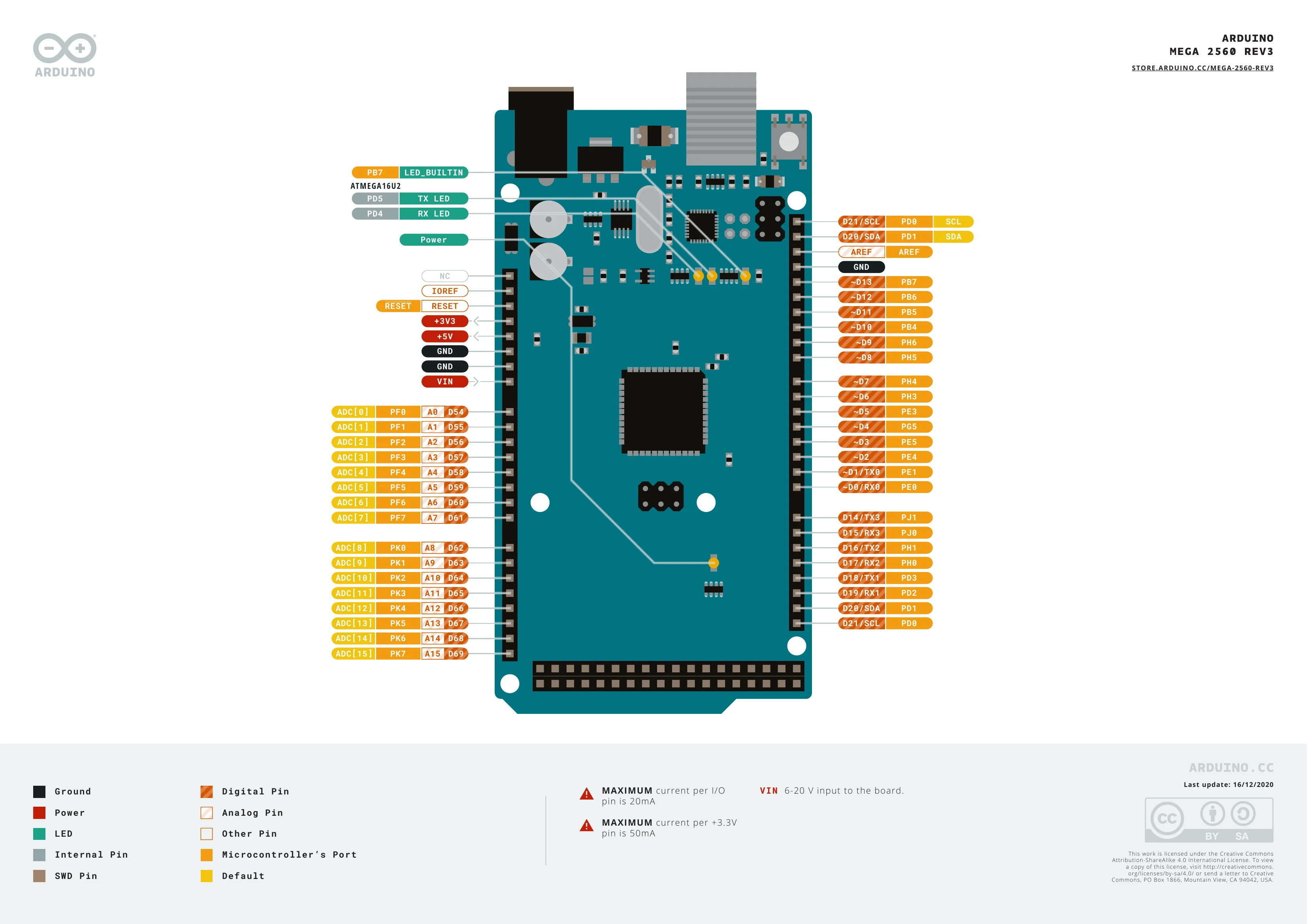
A microcontroller is a CPU, flash, RAM and peripherals (timers, ADC, serial ports, I/O pins) on one chip. The Mega is a board built around one, the ATmega2560, with USB, a voltage regulator and headers for every pin.
| Microcontroller | ATmega2560, 8-bit AVR, 16 MHz |
| Logic level | 5 V: HIGH = 5 V, LOW = 0 V |
| Digital I/O | Pins 0–53. Avoid 0 and 1, which carry the USB serial link. |
| PWM outputs | Pins 2–13 and 44–46, marked ~ |
| Analog inputs | A0–A15 |
| On-board LED | Pin 13, labelled L |
| Current per pin | 20 mA recommended, 40 mA absolute maximum |
The double header: pins D22–D53
The two-row header at the end of the board carries pins 22–53, with even numbers in one row and odd in the other. Example 3 wires the keypad here.
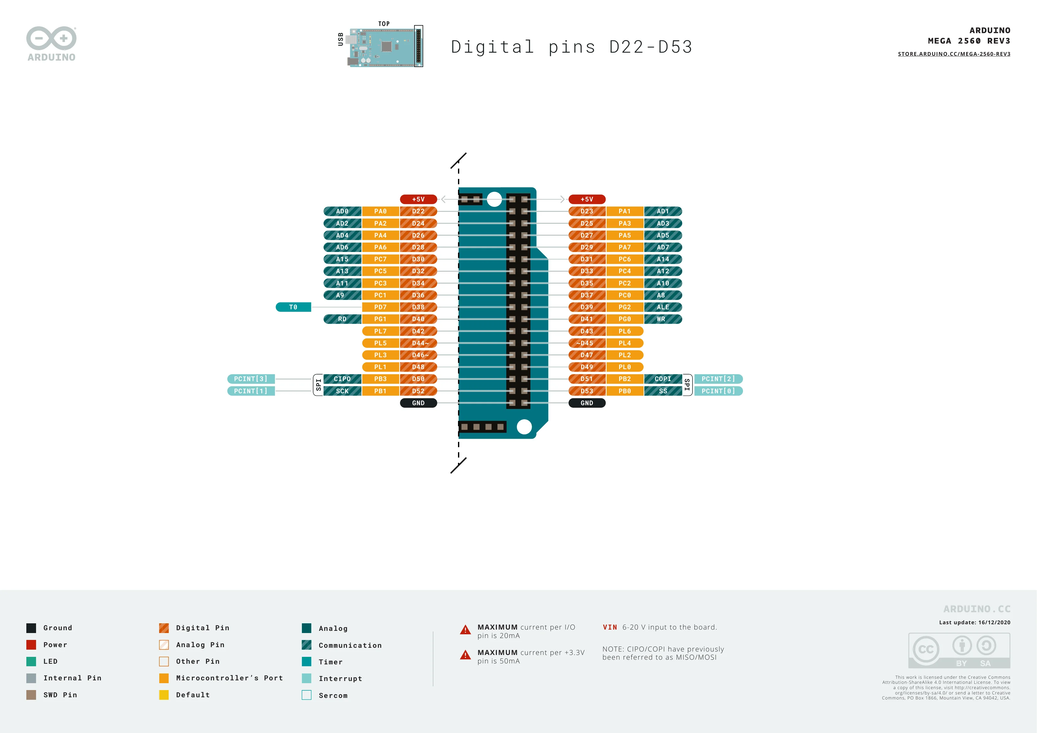
Pinout diagrams © Arduino, CC BY-SA 4.0. Full version: A000067 pinout (PDF).
Sketch structure
An Arduino program is called a sketch. It has no main(). Instead you write two functions, and the Arduino core calls them for you:
void setup() {
  // runs once, at power-up or reset: configure pins, start Serial
}

void loop() {
  // runs over and over, forever
}
Function quick reference
| Function | Effect |
|---|---|
pinMode(pin, mode) | Set pin to OUTPUT, INPUT or INPUT_PULLUP |
digitalWrite(pin, value) | Drive an output HIGH (5 V) or LOW (0 V) |
digitalRead(pin) | Read an input: HIGH or LOW |
analogWrite(pin, 0–255) | PWM output on a ~ pin: 0 is always off, 255 always on |
analogRead(A0) | Read an analog pin: 0–1023 for 0–5 V |
delay(ms) | Wait, doing nothing else |
millis() | Milliseconds since reset, as an unsigned long |
Serial.begin(9600) | Start the USB serial link at 9600 baud |
Serial.print(x) / Serial.println(x) | Send text or a number, without / with a newline |
LEDs
An LED conducts only one way: current flows from the anode (long leg, +) to the cathode (short leg, flat side of the rim, −). It also needs a series resistor, or it draws more current than the pin can supply. With about 2 V across a red LED, 220 Ω gives (5 − 2) / 220 ≈ 14 mA, which is bright and safe.
pin ──[ 220 Ω ]──▶|── GND
                anode  cathode
Push buttons and pull resistors
A tactile push button has four legs, connected in two pairs. The two legs on each long side are always joined. Pressing the button connects one pair to the other, and releasing it disconnects them again: the button is momentary, not a toggle.
An input pin connected only to a button floats while the button is up. It picks up noise and reads random values. A resistor gives it a defined idle level:
| Wiring | Idle (released) | Pressed | pinMode |
|---|---|---|---|
| Pull-down: 10 kΩ pin→GND, button pin→5 V | LOW | HIGH | INPUT |
| Pull-up: 10 kΩ pin→5 V, button pin→GND | HIGH | LOW | INPUT |
| Internal pull-up: button pin→GND, no resistor | HIGH | LOW | INPUT_PULLUP |
With a pull-up the logic is inverted: pressed reads LOW. INPUT_PULLUP saves the resistor, so it is what you use from now on.
Detecting one press
loop() runs thousands of times a second, so "the button is down" stays true for hundreds of loops. To act once per press, compare the current reading with the previous one and act only on the change, the edge:
int last = HIGH;                       // INPUT_PULLUP: released reads HIGH

void loop() {
  int now = digitalRead(BUTTON_PIN);
  if (last == HIGH && now == LOW) {    // falling edge: just pressed
    // ... do the thing once ...
    delay(50);                         // let the contacts stop bouncing
  }
  last = now;
}
The contacts bounce for a few milliseconds, so one press can look like several edges. The short delay(50) after an edge ignores them.
Timing without delay()
While delay() runs, the board does nothing else, so it cannot see a button press either. To blink and watch buttons at the same time, check the clock instead of waiting on it:
unsigned long lastToggle = 0;

void loop() {
  if (millis() - lastToggle >= interval) {
    lastToggle = millis();
    digitalWrite(LED_PIN, !digitalRead(LED_PIN));   // toggle
  }
  // ... the rest of loop() still runs every pass ...
}
Matrix keypads
A 4×3 keypad has 12 buttons but only 7 pins. The buttons sit where 4 row wires cross 3 column wires, and pressing one joins its row to its column. To find the key, the Keypad library drives one row at a time and reads which column follows it. You only call keypad.getKey(), which returns the character of a newly pressed key or NO_KEY.
Materials
- Arduino Mega 2560 and USB cable
- Breadboard and jumper wires
- 3 × LEDs, 3 × 220 Ω resistors
- 2 × push buttons, 1 × 10 kΩ resistor
- 4×3 matrix keypad
Examples
Upload each one as described in Arduino IDE → Upload a sketch.
Example 1: blink
// blink.ino: LED on pin 13 on for 1 s, off for 1 s, forever

const int LED_PIN = 13;           // also the on-board "L" LED
const int DELAY_MS = 1000;

void setup() {
  pinMode(LED_PIN, OUTPUT);
}

void loop() {
  digitalWrite(LED_PIN, HIGH);    // LED on
  delay(DELAY_MS);
  digitalWrite(LED_PIN, LOW);     // LED off
  delay(DELAY_MS);
}
With nothing wired, the on-board L LED blinks. Then add an external LED: pin 13 → 220 Ω → anode, cathode → GND. Both LEDs blink together.
Example 2: LED follows a button
Keep the LED on pin 13 and add a button with a pull-down resistor:
| From | To |
|---|---|
| Button, one side | 5 V |
| Button, other side | Pin 4 |
| 10 kΩ resistor | Pin 4 → GND |
// button.ino: LED on pin 13 follows a push button on pin 4
// (button to 5V, 10 kΩ pull-down from pin 4 to GND)

const int BUTTON_PIN = 4;
const int LED_PIN = 13;

void setup() {
  pinMode(LED_PIN, OUTPUT);
  pinMode(BUTTON_PIN, INPUT);     // the external resistor sets the idle level
}

void loop() {
  int state = digitalRead(BUTTON_PIN);   // HIGH while pressed, LOW when released
  digitalWrite(LED_PIN, state);
}
The LED is lit only while you hold the button. Pull the 10 kΩ out and touch pin 4's wire: the LED flickers on its own. That is a floating input.
Example 3: keypad to Serial Monitor
Install the Keypad library by Mark Stanley, Alexander Brevig (Arduino IDE → Install a library). Wire the keypad's 7 pins, R1–R4 then C1–C3, to Mega pins 22–28.
// keypad.ino: print every key pressed on a 4x3 keypad to the Serial Monitor
// Needs the "Keypad" library by Mark Stanley and Alexander Brevig.

#include <Keypad.h>

const byte ROWS = 4;
const byte COLS = 3;

char keys[ROWS][COLS] = {
  {'1', '2', '3'},
  {'4', '5', '6'},
  {'7', '8', '9'},
  {'*', '0', '#'},
};

byte rowPins[ROWS] = {22, 23, 24, 25};   // R1..R4
byte colPins[COLS] = {26, 27, 28};       // C1..C3

Keypad keypad = Keypad(makeKeymap(keys), rowPins, colPins, ROWS, COLS);

void setup() {
  Serial.begin(9600);
  Serial.println("Press a key:");
}

void loop() {
  char key = keypad.getKey();     // NO_KEY if nothing was pressed
  if (key != NO_KEY) {
    Serial.println(key);
  }
}
Open the Serial Monitor at 9600 baud and press keys.
Keypad pin order
Not every keypad puts its pins in the order R1–R4, C1–C3. If the keys print as the wrong characters or not at all, check the keypad's datasheet, or find the order with a multimeter in continuity mode. Then fix rowPins and colPins to match, rather than rewiring.
Lab work
Lab work 1: binary counter
Wire three LEDs (pins 2, 3 and 4) and one button using INPUT_PULLUP. Each press adds 1 to a counter, shown in binary on the LEDs: 000, 001, … 111, then back to 000.
Hints
- Count on the edge, as in Detecting one press, not on the level.
(count >> i) & 1is bit i ofcount, which is exactly theHIGH/LOWfor LED i.
Lab work 2: blink speed control
One LED blinks. Button A makes it blink faster and button B slower, in steps, within limits you choose, for example 100–1000 ms. Use INPUT_PULLUP for both buttons.
Hints
- With
delay()in the blink, presses are missed while the LED is waiting. Usemillis()timing. - Print the current interval with
Serial.println()so you can see each press register.
Lab work 3: keypad password
Extend Example 3 into a password lock, with all messages on the Serial Monitor:
- Pressing
*starts setting a 4-digit password. Digits typed after it are collected, and#saves them. - The sketch then asks for the password. The user types digits and confirms with
#. - If they match, print
Hello; otherwise printWrong passwordand ask again.
Never accept more than 4 digits: ignore extra digit keys.
Hints
- Keep a
modevariable (SETTING,ENTERING) and handle each key according to the current mode. This is a small state machine. - Store the digits in a
chararray plus a count, and compare them with a loop orstrncmp.
Common problems
| Symptom | Cause and fix |
|---|---|
| The LED never lights | It is in backwards: the long leg goes toward the pin. Or the resistor and LED are in the same breadboard row, so they are shorted. |
| The LED is very dim | The pin is still an INPUT. Call pinMode(pin, OUTPUT) in setup(). |
| The input changes on its own | It is floating. Add the pull resistor or use INPUT_PULLUP. |
| The LED is on when the button is up | You use a pull-up, so released reads HIGH. Invert your test. |
| The counter jumps by 2 or 3 per press | Bouncing, or counting the level instead of the edge. |
| The button reads as pressed all the time | Both wires are on legs that are always joined. Use diagonally opposite legs. |
| Presses are missed while the LED blinks | delay() is blocking. Use millis(). |
| Upload or Serial Monitor problems | See the setup troubleshooting. |
Things to try
- Wire four LEDs and make pairs alternate every second (the manual's TODO 1).
- Fade an LED on a
~pin by steppinganalogWrite()from 0 to 255 and back. - Show the counter of Lab work 1 on the Serial Monitor as well, in binary:
Serial.println(count, BIN).