
Registers, Timers, Interrupts and ADC
pinMode(), digitalWrite() and delay() hide the hardware. This experiment goes underneath them: you set a whole port with one register write, let a hardware timer call your code on schedule, let a button interrupt the program, and convert sensor voltages to numbers with the ADC.
Objectives
- Set and read a whole port with the
DDRx,PORTxandPINxregisters. - Configure Timer1 to raise an interrupt at a chosen interval.
- Handle a button with an external interrupt, and share data safely with
volatile. - Read a temperature sensor with
analogRead()and convert the result to volts and degrees.
Before the lab
Finish Experiment 5. This experiment uses its port registers from C. You need binary and hex: 0b00000111 is 0x07 is 7.
Background
Port registers in C
Experiment 5 set port bits one at a time from assembly. In C the same registers are plain variables, so a whole port is one assignment. As a reminder: DDRx bit 1 makes the pin an output, PORTx drives it (or turns on the pull-up of an input), and PINx reads it. Port A bits 0–7 are pins 22–29.
So DDRA = 0xFF; PORTA = 0xF0; makes all of port A outputs, pins 26–29 HIGH and 22–25 LOW, in two instructions instead of sixteen calls.
To change one bit and leave the rest alone, the way sbi and cbi do, use the bit operators:
| Code | Effect on bit n |
|---|---|
PORTA |= (1 << n); | Set it to 1 |
PORTA &= ~(1 << n); | Clear it to 0 |
PORTA ^= (1 << n); | Toggle it |
if (PINA & (1 << n)) | True if the pin reads HIGH |
1 << n is a number with only bit n set: 1 << 3 is 0b00001000.
7-segment displays
A 7-segment display is seven LEDs, named a to g, sharing one pin. On a common-cathode display that pin goes to GND and a segment lights when its own pin is HIGH. Wire segments a–g to port A bits 0–6, and one byte written to PORTA draws one digit:
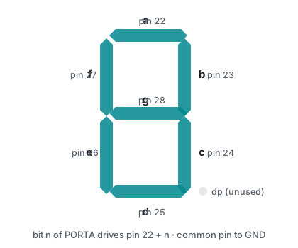
| Digit | PORTA | Digit | PORTA |
|---|---|---|---|
| 0 | 0x3F | 5 | 0x6D |
| 1 | 0x06 | 6 | 0x7D |
| 2 | 0x5B | 7 | 0x07 |
| 3 | 0x4F | 8 | 0x7F |
| 4 | 0x66 | 9 | 0x6F |
Each segment is an LED, so each needs its own series resistor.
Timer1
A timer is a hardware counter that counts clock ticks while your program does other things. Timer1 is 16-bit: it counts up to 65535, wraps to 0, and at that overflow can call an interrupt routine. The Mega's clock is 16 MHz, far too fast to count usefully, so a prescaler divides it first:
| Prescaler | TCCR1B bits | Tick | Full count (65536 ticks) |
|---|---|---|---|
| 1 | CS10 | 0.0625 µs | 4.1 ms |
| 8 | CS11 | 0.5 µs | 32.8 ms |
| 64 | CS11, CS10 | 4 µs | 262 ms |
| 256 | CS12 | 16 µs | 1.05 s |
| 1024 | CS12, CS10 | 64 µs | 4.19 s |
To overflow after a shorter time, start the count partway up. For an interrupt every 0.25 s at prescaler 256:
- One tick is 256 / 16 MHz = 16 µs.
- 0.25 s needs 0.25 / 16 µs = 15625 ticks.
- Start at 65536 − 15625 = 49911, the preload. Write it to
TCNT1at the start and again in every interrupt.
The registers involved:
| Register | Use here |
|---|---|
TCCR1A | 0: normal mode |
TCCR1B | Clock-select bits CS12..CS10: the prescaler. Any non-zero value starts the timer. |
TCNT1 | The count itself; write the preload here |
TIMSK1 | Bit TOIE1 enables the overflow interrupt |
ISR(TIMER1_OVF_vect) | The function that runs at each overflow |
Leave Timer0 alone
Timer0 drives millis() and delay(). Taking over Timer1 is safe, but it disables PWM on pins 11 and 12, and the Servo library, which use it.
External interrupts
Polling a button in loop() misses presses while the loop is busy. An external interrupt makes the hardware stop the program the moment the pin changes, run a short function (the ISR), and then resume where it left off.
attachInterrupt(digitalPinToInterrupt(pin), myISR, mode);| Interrupt pins on the Mega | 2, 3, 18, 19, 20, 21 |
mode | FALLING (HIGH→LOW), RISING, CHANGE (either), LOW (repeatedly while low) |
Rules for every ISR, timer or external:
- It takes no arguments and returns nothing. Keep it short: set a flag or change a counter, and let
loop()do the rest. delay()does not work in it, andmillis()does not advance while it runs.Serial.print()in an ISR can hang the board.- A variable that both the ISR and
loop()use must be declaredvolatile, or the compiler may keep a stale copy in a register. - A multi-byte variable (
int,long) can change halfway through reading it inloop(). Copy it betweennoInterrupts()andinterrupts().
The ADC
The ADC (analog-to-digital converter) turns a voltage on pins A0–A15 into a number. The Mega's is 10-bit with a 5 V reference, so analogRead() returns 0 for 0 V and 1023 for 5 V:
| Reading from voltage | reading = Vin × 1023 / 5 |
| Voltage from reading | Vin = reading × 5.0 / 1023 |
| Resolution | 5 V / 1023 ≈ 4.9 mV per step |
For example, 2.3 V reads as 2.3 × 10²³ / 5 ≈ 470. Write 5.0, not 5, or the division is done in integers and gives 0.
The TMP36 temperature sensor
The TMP36 has three legs and an output voltage that rises 10 mV per °C, with 0.5 V at 0 °C:
int reading = analogRead(A0);
float volts = reading * 5.0 / 1023;
float celsius = (volts - 0.5) * 100;| TMP36 leg (flat face toward you, legs down) | To |
|---|---|
| Left | 5V |
| Middle | A0 |
| Right | GND |
Room temperature reads about 0.75 V, 25 °C. Backwards, the sensor gets hot within seconds.
Materials
- Arduino Mega 2560 and USB cable
- Breadboard and jumper wires
- Common-cathode 7-segment display and 7 × 330 Ω resistors
- LED and 220 Ω resistor
- Push button
- TMP36 temperature sensor
Examples
Example 1: a digit from one register
Wire the 7-segment as in the figure: segment a–g pins through 330 Ω each to Mega pins 22–28, and the common pin to GND. Check your display's datasheet for which pin is which segment.
// ports.ino: blink a "7" on a common-cathode 7-segment, using port registers only
// Segments a..g on PORTA bits 0..6 = pins 22..28. Common pin to GND.

void setup() {
  DDRA = 0xFF;            // all 8 pins of port A are outputs
}

void loop() {
  PORTA = 0b00000111;     // segments a, b, c on: a "7"
  delay(1000);
  PORTA = 0x00;           // all segments off
  delay(1000);
}
A 7 blinks. Change 0b00000111 to the other values in the digit table to draw other digits.
Example 2: Timer1 overflow interrupt
No wiring: this uses the on-board LED.
// timer1.ino: toggle the on-board LED every 0.25 s from a Timer1 overflow interrupt
// loop() is empty: the timer does all the work.

const int LED_PIN = 13;
const unsigned int PRELOAD = 49911;   // 65536 - 15625: overflows after 0.25 s at prescaler 256

void setup() {
  pinMode(LED_PIN, OUTPUT);

  noInterrupts();               // no interrupts while the timer is half set up
  TCCR1A = 0;                   // normal mode
  TCCR1B = 0;
  TCNT1 = PRELOAD;
  TCCR1B |= (1 << CS12);        // prescaler 256: this also starts the timer
  TIMSK1 |= (1 << TOIE1);       // enable the overflow interrupt
  interrupts();
}

ISR(TIMER1_OVF_vect) {
  TCNT1 = PRELOAD;              // reload, or the next overflow takes 65536 counts
  digitalWrite(LED_PIN, !digitalRead(LED_PIN));
}

void loop() {
  // free for other work
}
The LED blinks, on 0.25 s and off 0.25 s, although loop() is empty. Change the prescaler to 1024 and work out the new period before you upload.
Example 3: external interrupt
Wire a push button between pin 2 and GND. Open the Serial Monitor at 9600 baud.
// interrupt.ino: count button presses with an external interrupt on pin 2
// Button between pin 2 and GND, internal pull-up.

const int BUTTON_PIN = 2;          // interrupt-capable: 2, 3, 18, 19, 20, 21
const int LED_PIN = 13;

volatile unsigned int presses = 0; // changed by the ISR, read by loop()

void onPress() {
  presses++;
}

void setup() {
  pinMode(LED_PIN, OUTPUT);
  pinMode(BUTTON_PIN, INPUT_PULLUP);
  attachInterrupt(digitalPinToInterrupt(BUTTON_PIN), onPress, FALLING);
  Serial.begin(9600);
}

void loop() {
  static unsigned int shown = 0;
  noInterrupts();                  // copy the shared variable in one piece
  unsigned int now = presses;
  interrupts();

  if (now != shown) {
    shown = now;
    Serial.println(now);
    digitalWrite(LED_PIN, now % 2); // LED toggles on each press
  }
}
Each press prints the count and toggles the LED. Sometimes one press counts 2 or 3: that is contact bounce, which the interrupt is fast enough to see. Lab work 1 deals with it.
Lab work
Each lab work starts from a sketch that already works except for a few lines marked TODO. Copy it into the IDE, fill in the TODOs, and upload.
Lab work 1: pause and resume
The 7-segment counts 0 → 9 → 0, one step every second, driven by Timer1. Pressing the button pauses the count; pressing it again resumes it.
Keep the Example 1 display wiring and the Example 3 button on pin 2.
// lab1-starter.ino: Lab work 1. Fill in the four TODOs; everything else is done for you.
// 7-segment on pins 22..28 (as in Example 1), button between pin 2 and GND.

const byte digits[10] = {0x3F, 0x06, 0x5B, 0x4F, 0x66, 0x6D, 0x7D, 0x07, 0x7F, 0x6F};
const int BUTTON_PIN = 2;
const unsigned int PRELOAD = 0;   // TODO 1: the preload for 1 second at prescaler 256

volatile byte count = 0;          // the digit on the display
volatile bool paused = false;     // true while the count is stopped

void onPress() {                  // runs on every button press
  static unsigned long last = 0;
  if (millis() - last < 200) return;   // a second "press" within 200 ms is bounce: ignore it
  last = millis();
  // TODO 4: flip paused (true becomes false, false becomes true)
}

void setup() {
  DDRA = 0xFF;                    // port A: all outputs
  PORTA = digits[0];              // show 0

  pinMode(BUTTON_PIN, INPUT_PULLUP);
  attachInterrupt(digitalPinToInterrupt(BUTTON_PIN), onPress, FALLING);

  noInterrupts();                 // Timer1 set up exactly as in Example 2
  TCCR1A = 0;
  TCCR1B = 0;
  TCNT1 = PRELOAD;
  TCCR1B |= (1 << CS12);
  TIMSK1 |= (1 << TOIE1);
  interrupts();
}

ISR(TIMER1_OVF_vect) {            // runs once a second
  TCNT1 = PRELOAD;
  // TODO 2: if the count is not paused, add 1 to count. After 9 it goes back to 0.
  // TODO 3: show count on the display
}

void loop() {
  // nothing: the two interrupts do all the work
}
Hints
- TODO 1: follow the three steps in Timer1, but for 1 s instead of 0.25 s.
- TODO 2:
if (!paused) { ... }. Inside,count = (count + 1) % 10;adds 1 and wraps 9 back to 0. - TODO 3: one line:
PORTA = digits[count]; - TODO 4:
paused = !paused;
Check your TODO 1
At prescaler 256 one tick is 16 µs, so 1 s is 62500 ticks, and the preload is 65536 − 62500 = 3036.
Lab work 2: temperature alarm
Print the temperature every second, and light an LED when it gets warmer than a threshold. Warm the sensor between your fingers to test it.
Wire the TMP36 as in its section, and an LED on pin 8 through 220 Ω.
// lab2-starter.ino: Lab work 2. Fill in the three TODOs.
// TMP36 output on A0, LED on pin 8 through 220 Ω.

const int LED_PIN = 8;
const float T_ON = 0;             // TODO 1: your room temperature + 2 (°C)

void setup() {
  pinMode(LED_PIN, OUTPUT);
  Serial.begin(9600);
}

void loop() {
  int reading = analogRead(A0);
  float volts = reading * 5.0 / 1023;
  float celsius = 0;              // TODO 2: convert volts to °C

  Serial.print(celsius);
  Serial.println(" C");

  // TODO 3: turn the LED on if celsius is above T_ON, off if it is not

  delay(1000);
}
Hints
- TODO 1: upload once with
T_ONat 0 to read your room temperature, then set it 2 °C higher. - TODO 2: the formula is in The TMP36.
- TODO 3: an
if/elsewithdigitalWrite(LED_PIN, HIGH)anddigitalWrite(LED_PIN, LOW).
Common problems
| Symptom | Cause and fix |
|---|---|
| No segment lights | The display is common anode, not common cathode: its common pin goes to 5V and the codes are inverted (PORTA = ~digits[i]). |
| Wrong segments light | The display's pinout differs. Find each segment with a resistor from 5V, then rewire to match a–g on 22–28. |
| The digit is dim or one segment is brighter | A segment shares a resistor or has none. Each segment needs its own. |
| The timer interrupt never runs | TIMSK1 not set, interrupts() missing, or TCCR1B left 0 so the timer never starts. |
| The timer period is wrong | The preload is not reloaded in the ISR, or the prescaler bits are wrong. Check against the prescaler table. |
The value set in an ISR never changes in loop() | The variable is not volatile. |
attachInterrupt() does nothing | The pin cannot interrupt. Use 2, 3, 18, 19, 20 or 21, and wrap it in digitalPinToInterrupt(). |
| The temperature is nonsense, or the TMP36 is hot | It is in backwards. Unplug it at once and check the legs against the table. |
| Temperature reads −50 °C | The output leg is not on A0, or 5 was written instead of 5.0. |
Things to try
- Use CTC mode for Timer1 instead of the preload: set
WGM12inTCCR1B, put the count inOCR1A, enableOCIE1AinTIMSK1, and useISR(TIMER1_COMPA_vect). The ISR no longer reloads anything. - Read the button in Lab work 1 straight from
PINE: pin 2 is bit 4 of port E (PE4). - In Lab work 2, a temperature sitting right at
T_ONflickers the LED on and off. Turn it off only belowT_ON − 1: that gap is called hysteresis. - Swap the TMP36 for an LDR (light-dependent resistor) in a divider: LDR from 5V to A0, 10 kΩ from A0 to GND. More light gives a higher reading. Light an LED when it gets dark.